A passport with an aerodynamic characteristic is usually attached to the fan supplied for the ventilation system, from which it can be determined what the full and static pressure the fan should give for a given performance.
How in real conditions (on site) can you measure the performance of a fan in a real network?
Total fan pressure: p V = p 20 - p 10
p 20 - total pressure at the fan outlet;
p 10 - total pressure at the fan inlet.
Static fan pressure: p SV = p 2 - p 10
p 2 - static pressure at the fan outlet.
These formulas are outwardly very simple, and in most cases under laboratory conditions, there are no problems with measuring the aerodynamic characteristics of the fans, if there is a clear agreement on the content of these terms and methods for measuring these values. For this, there are domestic, foreign and international standards for measuring the aerodynamic characteristics of fans. They are different in some details, therefore when considering aerodynamiccharacter foreign fans need to figure outdirectory dataconditions and measurement procedure to eliminate possible errorsinterpretations results. For example, in domestic installations the mostoften implemented here are tests A or C when speedhead pressure is determined recalculated from the performance of the fan. In foreign installations, for example, scheme B is also encountered, when direct measurement of the total pressure behind the fan is made. Taking into account the uneven velocity fields at the fan outlet, the B-scheme method can give slightly different results on the total fan pressure. One more example. When testing axial fans, the exit area can be determined by the diameter of the impeller or by the diameter of the impeller minus the sleeves. This results in different areas of output and, accordingly, different total pressure of the fan.
If the fan is already installed and connected to the network, then the measurement of its aerodynamic parameters (pressure and performance) may cause some difficulties. Consider a number of features of such measurements.
To determine the fan pressure, first of all, it is necessary to measure the total pressure in the duct in front of the fan . Formally, the measuring section should be at a distance of at least 2D from the fan inlet (D - diameter or hydraulic diameter of the duct). In addition, there should be a segment of a direct duct with an unperturbed flow of at least 4 length in front of the measuring section.D ). As a rule, such conditions of entry are rare. If a rotary knee or a cap or other device located in front of the fan entrance, disturbing the uniform flow structure in the measuring section, it is necessary to install a flow-leveling grid (honeycomb) before the measuring section. If the measuring section meets the measurement requirements, they can be performed in accordance with the procedure described above. Using the total pressure input to the receiver duct, the total pressures are measured at a number of cross-section points, and the corresponding average total pressure in the section is determined. If you simultaneously measure the velocity head, you can determine the fan performance by integrating the obtained local flow rates over the measuring area. section. If the fan hasfree inlet, the total inlet pressure p 10 is equal to the ambient pressure (i.e. the overpressure is zero).
For measuring the total pressure behind the fan it is important to choose the most appropriate position of the measuring section, since the flow structure at the fan outlet is not uniform over the section and depends on the type of fan and its mode of operation. The velocity field in cross section at the exit from the fan in some cases may have return current zones and, as a rule, is not stationary in time. If there are no flow straightening grids in the duct, the flow inhomogeneities can spread quite far downstream (up to 7-10 calibers). If there is a diffuser with a large opening angle (tear-off diffuser) or a swivel knee behind the fan, then the flow after them can also be very non-uniform across the section. Therefore, we can offer the following measurement method. Choose one measuring section directly behind the fan and scan it in detail with a probe, measuring the total pressure and velocity head, and determine the average total pressure and fan performance. Performance compared with the corresponding value obtained from measurements in the input measuring section of the fan. An additional measuring section should be selected on the nearest straight section of the duct at the distance of 4-6 calibers from the beginning of this section (at the maximum possible distance from the beginning of the section if its length is shorter). Using a probe, measure the distribution over the cross-section of total pressure and velocity head and determine the average total pressure and fan performance. From the obtained total pressure, subtract the calculated value of losses in the duct section from the fan outlet to the measuring section, this will be the total pressure at the fan outlet. Compare the performance of the fan with the values obtained for entering the fan and directly on the course. Conditions that are usually satisfactory for measuring fan performance are easier to provide at the inlet, so you need to choose a cross section on your course, which is more suitable for the performance of the input section. In the case of a roof fan, there is no pressure network, and measurements are taken only at the fan inlet. In this case, the velocity head at the exit from the fan is completely lost, and for it the characteristic is measured only by static pressure.
Measurement of the aerodynamic parameters of the fan is associated with another difficulty - the non-stationarity of the flow parameters. In pneumometric measurements, various types of dampers are used to obtain reliable data - devices that smooth pressure pulsations. There are electronic pressure gauges with mathematical time averaging on the market of measuring equipment.
Donbass State Machine-Building Academy
METHODICAL INDICATIONS
to laboratory work on the course
"Heat engineering and power engineering"
"Theoretical fundamentals of heat engineering"
for technical students
Approved
at the meeting of the department
chemistry and labor protection.
Protocol number 5
Kramatorsk 2004
UDC 621.1.016 (175.8)
Guidelines for laboratory work on the course "Heat Engineering and Heat Power Engineering" and "Theoretical Foundations of Heat Engineering" for students of technical specialties / Comp .: Yu.V. Menafova, S.А. Konovalova. - Kramatorsk: DGMA, 2004. - 92 p.
Compiled by: Yu.V. Menafov, Art. prep.
S.A. Konovalova, Assist.
Ed. for the issue of A.P. Avdeenko, prof.
Introduction
These guidelines are a teaching tool for laboratory work on heat engineering and power engineering by students of engineering specialties.
The purpose of the laboratory workshop is to consolidate the theoretical knowledge gained by students in lectures, familiarize themselves with the design and principle of operation of thermal devices, acquire skills in operating equipment, and determine the basic characteristics of devices.
The first lesson with students is instructed in safety.
In preparation for each laboratory work student is necessary:
to study theoretical material on the relevant topic with the help of methodical instructions and special literature indicated in the list of references;
study the order of the experiment;
give answers to all test questions;
issue a report (in the absence of a report, the student is not allowed to perform laboratory work).
Preparation of the report is made on separate sheets and must necessarily contain the name of the work, the purpose of the work, the scheme of the laboratory setup with an indication of all its constituent parts and a table in which the measurement results will be entered.
At the lesson, students pass the theory on the relevant topic, perform laboratory work, do the necessary calculations, build graphs, if necessary, and draw conclusions.
A well-formed report at the end of the lesson is signed by the teacher.
Lab 1
DETERMINATION OF CHARACTERISTICS OF A CENTRIFUGAL FAN
Objective
Examine the design and operation of the centrifugal fan and determine the characteristics of the fan. Find the optimal mode of operation of the fan.
General information
Machines designed to compress gas or steam are called compressors.Depending on the design and principle of operation, the compressors are divided into reciprocating, rotary, centrifugal and axial.
An important quality characteristic of compressors is powerboost pressure equal to the ratio of the gas pressure behind the compressor P 2 to the gas pressure before the compressor P 1:
 . (1.1)
Depending on the magnitude of the degree of pressure increase compressors have different purposes. When = 1.0 ... 1.1, compressors are called fans, the main purpose of which is to move gases; when = 1.1 ... 4.0 - by blowers or blowers, and at 4.0, by compressors themselves.
Fans- these are blower machines that create a certain pressure and serve to move the air at a pressure loss in the ventilation network of not more than 12 kPa.
Depending on the pressure developed, the fans are divided into the following groups:
low pressure - up to 1kPa with a wheel peripheral speed of 23 ... 55 m / s;
medium pressure - 1 ... 3 kPa with a peripheral speed of the wheel of 40 ... 100 m / s;
high pressure - 3 ... 12kPa with a peripheral speed of the wheel of 100 ... 150 m / s.
Fans of low and medium pressure are used in installations of general and local ventilation, for dryers and furnaces. High-pressure fans are mainly used for technological purposes, for example, for blowing into cupolas, in sintering plants, for supplying air to the injectors, in filter cleaning systems and in pneumatic mail systems.
The most common are axial and centrifugal fans.
An axial fan is a blade wheel located in a cylindrical case, during rotation of which the air entering the fan moves in the axial direction under the action of the blades. Benefitsaxial fans are simplicity of design, the ability to effectively control performance over a wide range by turning the wheel blades, high performance, reversibility of work. The disadvantages include a relatively small amount of pressure and increased noise. Most often, these fans are used with low resistances of the ventilation network (up to about 200 Pa), although it is possible to use these fans with large resistances (up to 1 kPa).
Centrifugal fan(Fig.1.1) consists of an impeller 1 with blades 2, mounted on the shaft 3 of the electric motor (not shown in the picture), the inlet or suction nozzle 4, the discharge nozzle 5 and the fan case 6.

Figure 1.1 - Diagram of a centrifugal fan
The principle of operation of a centrifugal fan is as follows. When the impeller 1 rotates, the air particles are entrained by the blades 2 into rotational motion, while centrifugal forces act on the air particles, which are directed from the center to the walls of the casing 6. Thus, each air particle makes a complex movement: on the one hand, it moves along the blade, and on the other - rotates with the impeller around its axis. Since air particles move from the center to the casing wall, a vacuum is created in the center of rotation and in the suction inlet 4, i.e. the air pressure is less than the atmospheric pressure. Under the action of the pressure difference, new air particles from the surrounding atmosphere enter the suction nozzle. Thus, polluted air is removed from any source in engineering, metallurgical and other workshops.
Particles of air, thrown away from the center of rotation to the fan casing, move along the casing and enter the discharge nozzle 5. At the same time, air is compressed, its pressure increases and becomes more atmospheric.
At constant speed, the centrifugal fan operation is characterized by the following parameters:
volume flow of transported gas - performanceV, m 3 / s;
pressure drop("head") created by the fan - the difference between the total pressures at the inlet (in the suction pipe) and at the outlet (in the discharge pipe) of the fan - ΔР at Pa
 , (1.2)
where  - total pressure at the outlet (in the discharge pipe) of the fan, Pa;
 - total pressure at the inlet (in the suction inlet) of the fan, Pa;
efficiencyη The ratio of the power required to move the air to the power actually spent by the fan:
 ;
(1.3)
;
(1.3)
fan power consumption N at W
At centrifugal fans parameters V,ΔР at and N at interconnected, and a change in one of these quantities causes a change in the others.
Graphic dependencies ΔР at = f 1 ( V),N at = f 2 ( V),η = f 3 ( V) called fan performance. They clearly reflect the features of the fan and allow you to choose the most economical fan for this duct. Based on theoretical calculations, these characteristics cannot be obtained with sufficient accuracy. Therefore, in practice, apply the characteristics of the fans, obtained experimentally. Figure 1.2 shows typical characteristics of a centrifugal fan at constant impeller speed n(rpm).
The value of maximum efficiency determines the decisive quality of the fan - economy. The performance of the fan, the corresponding maximum efficiency, is called optimal, and the corresponding mode of operation of the fan - optimal.

Figure 1.2 - Full fan performance
The most important is the curve of the relationship between pressure and performance P– V- so-called pressure characteristicfan ( pressure characteristic). To determine it, it is necessary to make measurements of the total pressure at the fan inlet and outlet for various values of performance.
Total pressurerepresents the algebraic sum of static and dynamic pressures:
R floor = P st + P din (1.4)
Static pressure- is the pressure difference between the gas inside the pipeline and the surrounding air. At the fan inlet, the static pressure is less than atmospheric, and therefore has a negative value. At the fan outlet, the static pressure is greater than atmospheric and has a positive sign.
Dynamic, or speed pressuredepends only on the velocity of the gas and is always positive. Is determined by the dynamic pressure by the formula
 (1.5)
(1.5)
where ρ - gas density, kg / m 3;
ω - gas velocity, m / s.
In practice, the pressure in the pipeline can be measured using a U-shaped pressure gauge and pneumometric tube.
When measuring pressure with a liquid U-shaped manometer, the measured medium with pressure R but It is connected with a metal or rubber tube with one knee of the manometer, and the second knee - with the atmosphere having barometric pressure R b . Fluid height hmeasures excess pressure (Figure 1.3, but)
R huts = hρg, (1.6)
Where ρ - density of the liquid, kg / m 3;
g- gravitational acceleration, m / s 2.
Water or alcohol is most often used as a working fluid. The measurement accuracy of the U-shaped manometer with the correct reading of the liquid levels in the tubes is quite high. The readout of liquid manometers is shown in Figure 1.3, b,at.
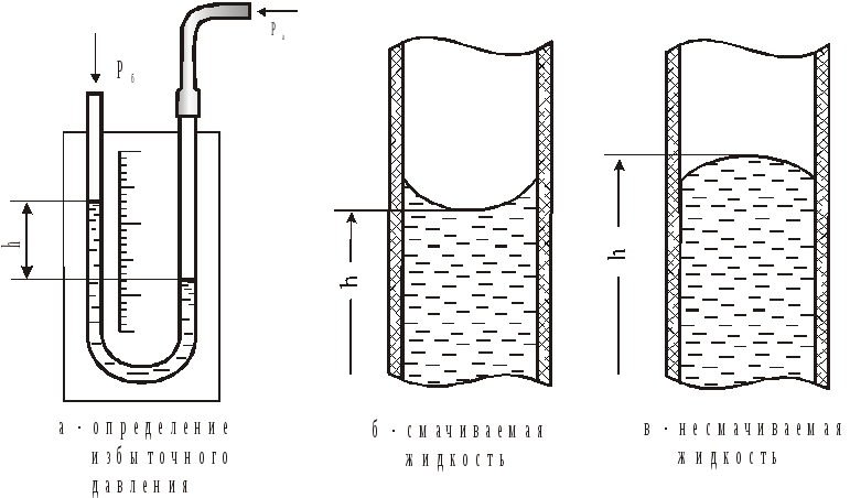
Figure 1.3 - Measurement of pressure with a liquid U-shaped manometer
The total pressure in the fan can be measured using an open pneumometric tube (Pitot tube), set against the flow (Figure 1.4, but), and static pressure - with the help of a tube or a hole in the pipeline, located perpendicular to the flow (Figure 1.4, b).
If both tubes are connected to the opposite ends of the manometer, then the difference in the levels of the working fluid in the manometer's knees will show the difference between the total and static pressure at a given point of flow, that is, the dynamic pressure (Fig. 1.4, at).
The total pressure drop is determined by using two bent tubes placed opposite to the air flow in two sections of the channel (Fig. 1.4, g). The static pressure drop is determined using two tubes located in the channel perpendicular to the direction of air movement (Fig. 1.4, d).

Figure 1.4 - Determination of pressure and pressure drops using
U-shaped manometer
For fan performance determinationuse pneumometric tubes or choke devices - withcontraction devices. Tapering devices can be used to measure the flow rate of any single-phase media, they can be installed in pipelines of any diameter; The temperature and pressure of the measured medium can be practically any value. It is very significant that the calibration characteristic of standard narrowing devices can be determined by calculation.
In this work, a throttle device is used to determine the air flow ( flow washer). The principle of using throttle instruments for measuring gas flow can be understood on the schedule of pressure distribution when installing a diaphragm in the pipe (Fig. 1.5)
We put in the pipeline with a diameter Ddiaphragm, which is a washer with a hole d, and measure the pressure in the pipeline to the diaphragm and beyond. When the pipeline narrows, the air speed increases from ω 1 before ω 2 , as a result of which, according to Bernoulli’s law, pressure drops from R 1 before R 2 . Behind the diaphragm, the air velocity decreases, and the pressure increases to R 3 but R 3 <R 1 that is, there is a pressure drop across the puck P sh = P 1 -R 3 which is proportional to the square of the air velocity. Knowing the diameter dwasher openings, you can determine the gas consumption in cubic meters per second:
V=
c  ,
(1.7)
,
(1.7)
where with- expenditure ratio of the diaphragm. For the flow meter used in this installation, with= 0.64 · 10 -2.

Figure 1.5 - Choke gas diaphragm and the nature of change
throttling pressure
Fan performance can be adjusted in various ways. One of the most economical ways - changing the number of revolutions of the impeller - has not yet been widely adopted due to the difficulties associated with changing the number of revolutions of the electric motor. The most widely used method of throttling the valve, having a low efficiency. In this work, performance control will be performed using the valve installed on the inlet nozzle.
Installation Description
The laboratory unit (Fig. 1.6) consists of a centrifugal fan 1, an asynchronous motor 2, a suction pipe 3, a damper 4, a discharge pipe 5, a pipe 6 and a flow meter 7. To measure the differential pressure at the inlet and outlet of the fan, they are bent at a right angle pneumometric tubes 8 and 9, fixed in the inlet and discharge nozzles and attached to a U-shaped manometer. The differential static pressure on the flow meter washer is measured using direct pneumometric tubes 10 and 11, mounted perpendicular to the pipeline before and after the washer 7 and connected to the pressure gauge 12.
Backward curved blades (impeller B):the volume of air supplied by the fan with the backward curved blades depends significantly on the pressure. Not recommended for polluted air. This type of fan is most effective in the narrow spectrum located on the left side of the fan curve. Up to 80% efficiency is achieved while maintaining a low fan noise level.
Rejected straight shoulder blades: fans with this blade shape are well suited for polluted air. Here you can achieve 70% efficiency. Direct radial blades (impeller R): The shape of the blades prevents sticking of contaminants to the impeller even more effectively than when using the impeller P. With this type of blade, an efficiency of more than 55% is achieved. Forward curved blades (impeller F): Changes in air pressure have a negligible effect on the volume of air supplied by radial fans with forward curved blades. The impeller F is smaller than, for example, impeller B, and the fan takes, respectively, less space. Compared to impeller B, this type of fan has optimal performance on the right side of the fan performance graph. This means that if you prefer a fan with a paddle wheel F rather than B, you can choose a smaller fan. In this case, you can achieve an efficiency of about 60%.Axial fans
The simplest type of axial fans are propeller fans. Freely rotating axial fans of this type have very low efficiency, and therefore most axial fans are built into the cylindrical case. In addition, the efficiency can be improved by strengthening the guide vanes directly behind the impeller. The level of efficiency can be raised up to 75% without guide blades and up to 85% with their use.
Air flow through axial fan:
Diagonal fans
The radial impeller causes an increase in static pressure due to the centrifugal force acting in the radial direction. An axial impeller does not produce equivalent pressure, since the air flow is normally axial. Diagonal fans are a mix of radial and axial fans. The air moves in the axial direction, and then in the impeller it is deflected by 45 °. The radial velocity component, which is increased by such a deviation, causes a slight increase in pressure through centrifugal force. You can achieve efficiency up to 80%.
Air flow through a diagonal fan:

Diametric fans
In diametrical fans, air flows directly along the impeller, and both incoming and outgoing flows are located around the impeller perimeter. Despite its small diameter, the impeller can supply large volumes of air, and therefore is suitable for use in small ventilation systems, such as an air curtain. The level of efficiency can reach 65%.
Air flow through a diametrical fan:

GOST 10616-90
(ST SEV 4483-84)
G82 group
STATE STANDARD OF THE UNION SSR
RADIAL AND AXIAL FANS
Dimensions and parameters
Radial and axial fans.
Dimensions and parameters
Valid from January 1, 1991
INFORMATION DATA
1. DEVELOPED AND INTRODUCED BY THE USSR Ministry of Construction, Road and Municipal Engineering
DEVELOPERS
G.S. Kulikov, V.B. Gorelik, V.M. Litovka, A.T. Pikhota, A.M. Rozhenko, N.I. Vasilenko, T.Yu. Naidenova, A.A. Piskunov, I.S. Berezhnaya, E.M. Zhmulin, L.A. Maslov, TS Solomakhova, TS Fenko, A.Ya. Sharipov, V.A. Spivak, M.S. Granovsky, M.V. Fradkin
2. APPROVED AND INTRODUCED BY Resolution of the USSR State Committee for Product Quality Management and Standards No. 591 of March 27, 2010.
3. The term of the first inspection is 1995.
inspection frequency - 5 years
4. The standard is fully consistent with ST SEV 4483-84.
5. VZAMEN GOST 10616-73
6. REFERENCE REGULATORY TECHNICAL DOCUMENTS
Item number, application |
|
GOST 8032-84 | |
2.11; 2.14; attachment |
|
GOST 12.2.028-84 |
This standard applies to single and double radial fans and axial single and multistage fans for air conditioning, ventilation, and other production purposes that increase the absolute total pressure of the flow by no more than 1.2 times and create a total pressure of up to 12000 Pa with a density of a floating medium of 1.2 kg / m.
The standard does not apply to fans that are built into air conditioners, as well as other equipment.
1. MAIN DIMENSIONS
1.1. The size of the fan is characterized by its number. The fan number is taken to be the value corresponding to the nominal diameter of the impeller, measured on the outer edges of the blades and expressed in decimeters. For example, a fan with = 200 mm is denoted by No. 2, = 630 mm - by No. 6.3, etc.
1.2. Nominal diameters of impellers, diameters of suction openings of radial (Fig. 1a) and axial (Fig. 1b) fans fitted with manifolds, and diameters of the discharge openings of axial fans fitted with diffusers should be selected from a number of values corresponding to the R20 GOST 8032 series specified in tab. one.


If necessary, the use of a number of R80.
Table 1
Fan sizes
Fan number | |
1.3. Fans of different numbers and designs, made by the same aerodynamic scheme, are of the same type.
2. AERODYNAMIC PARAMETERS
2.1. The capacity (volume flow) of the fan, (m / s) is taken as the volumetric amount of gas entering the fan per unit of time, related to the conditions of entry into the fan (see annex).
2.2. The total pressure of the fan (Pa) is taken as the difference between the absolute total pressure of the flow at the exit from the fan and before entering it at a certain gas density.
2.3. The dynamic pressure of the fan (Pa) is taken as the dynamic pressure of the flow at the exit from the fan, calculated from the average speed in the output section of the fan.
2.4. The static pressure of the fan (Pa) is taken as the difference of its total and dynamic pressure.
2.5. The power (kW) consumed by the fan is taken as the power at the fan shaft without taking into account losses in bearings and drive elements.
2.6. For the full efficiency of the fan, the ratio of the net power of the fan, equal to the product of the total pressure of the fan and its performance, to the power consumed by the fan is taken.
2.7. The static fan efficiency is taken as the ratio of the useful power of the fan, equal to the product of the static pressure of the fan and its performance, to the power consumption.
2.8. High speed [(m / s) Pa] and overall size [(m / s) Pa] of the fan are criteria for evaluating the suitability of the fan in the mode given by,, and speed, and serve to compare different types of fans.
2.9. The dimensionless parameters of the fan are performance factors, total and static pressure, as well as power consumption.
2.10. The aerodynamic qualities of the fan should be assessed according to the aerodynamic characteristics expressed in the form of graphs (Fig. 2) depending on the total and static and (or) dynamic pressures developed by the fan, the power consumption of the full and static efficiency on the performance at a certain gas density before entering the fan and constant the frequency of rotation of its impeller. The graphs should indicate the dimensions of the aerodynamic parameters.

It is allowed to build aerodynamic characteristics at a rotational speed that varies depending on performance, with an indication of this dependence () on the graph. Instead of curves and the graph can indicate the curve of the dynamic pressure of the fan.
Allowed in the construction of the aerodynamic characteristics of the curves; and do not specify.
2.11. The aerodynamic characteristics of the fan should be based on the data of aerodynamic tests carried out in accordance with GOST 10921, indicating one of the four types of connection of the fan to the network (A, B, C, D), taken from Table. 2
table 2
Connection type | Description of the type of connection |
|
fan | Suction side of the fan | Fan discharge side |
Free suction | Free flow |
|
Free suction | Network connection |
|
Network connection | Free flow |
|
Network connection | Network connection |
|
2.12. For general-purpose fans, aerodynamic characteristics should be given, corresponding to operation in air under normal conditions (density 1.2 kg / m, barometric pressure 101.34 kPa, temperature plus 20 ° С and relative humidity 50%).
2.13. For fans moving air and gas that has a density different from 1.2 kg / m, additional scales for the values,,, corresponding to the actual density of the fluid being moved should be given on the graphs.
2.14. For fans that create a total pressure exceeding 3% of the absolute total pressure of the flow before entering the fan, when calculating the aerodynamic characteristics, corrections should be introduced to take into account the compressibility of the moving gas according to GOST 10921.
2.15. For general-purpose fans designed to work with the network connected to them, the working part of the characteristic should be that part of it, on which the value of the total efficiency. The working section of the characteristic must also satisfy the condition for ensuring stable operation of the fan.
2.16. For fans operating at different rotational speeds, the working sections of the curves constructed on a logarithmic scale should be given, on which lines of constant values of efficiency, power should be plotted, the circumferential speed of the impeller and its rotational speed are indicated (Figure 3).

2.17. Dimensional aerodynamic characteristics, which are graphs (Fig. 4) of the dependence of the total and static pressures, power, total and static efficiency factors on the performance factor, are used to calculate dimensional parameters and to compare different types of fans.

The graphs should indicate the values of the fan speed (Fig. 4) or lines of constant values (Fig. 5), as well as the diameter of the impeller and the speed at which the characteristic was obtained.
LECTURE number 7Centrifugal fans
Plan
7.1 Basic Terms and Definitions
7.2 Fan classification
7.3 Layout schemes
7.4 Purpose and scope of the fans
7.1 Basic Terms and Definitions
Centrifugal fans are machines for moving pure gases and mixtures of gases with fine solid materials, having a degree of pressure increase of not more than 1.15 at a flux density of 1.2 kg / m 3. A characteristic feature of a centrifugal fan is an increase in pressure due to the work of the centrifugal force of gas moving in the impeller from the center to the periphery.
With a slight increase in gas pressure, a change in its thermodynamic state can be neglected. Therefore, the theory of the machine for an incompressible medium is applicable to centrifugal fans.
The standard has the following terms:
fan - unit consisting of a housing, a rotor, guides, straighteners with a collector and an inlet box attached to them;
fan installation - a fan or two fans with air inlet and outlet elements attached to them, inlet and outlet channels, diffusers.
fan feed Q - the amount of air entering the unit of time through the living section of the entrance to the fan, m 3 / s.
nominal fan feed Q Mr. - feed in the mode of maximum static efficiency, m 3 / s.
total fan pressure P V - the difference of the total gas pressure at the exit from the fan and before entering it, Pa.
fan static pressure P SV is the difference between the total pressure of the fan and the dynamic pressure behind it, Pa.
rated static fan pressure P SV nom is the static pressure of the fan in the mode of maximum static efficiency, Pa.
useful power N is the total increment of the specific energy per unit of time received by the air flow in the fan, kW,
where β - air compressibility factor in the fan (β = 1.01 - 1.07).
power consumption N B - power at the fan shaft, kW.
Centrifugal fans are widely distributed in industry and public utilities for ventilation of buildings, aspiration of harmful substances in technological processes.
In heat and power plants, centrifugal fans are used to supply air to the combustion chambers of boilers, to move fuel mixtures in dust preparation systems, to suck out flue gases and transport them to the atmosphere.
7.2 Fan classification
In the literature there is no single generally accepted classification of centrifugal fans. However, fans can be classified according to a number of characteristics: rapidity, pressure created, layout, drive type, purpose, etc.
By speed, the fans can be divided into small (N y = 11 30), medium (N y = 30 60) and large (N y = 6081) fans.
Low speed fans . They have small entrance diameters, small wheel width, small width and opening of the spiral casing. The blades of the impeller can be bent in the direction of its rotation and against this direction. The lower the fan speed, the less the shape of the blade affects its aerodynamic characteristics. The maximum efficiency of these fans does not exceed 0.8. Dimension varies in the range of D y = 6 1,7.
Medium speed fans . Significantly distinguished by their geometric and aerodynamic parameters. Fans with a drum-type wheel and a large entrance diameter, whose pressure coefficients are close to the maximum possible (ψ ≈ 3), have average speed. These fans have maximum efficiency of max. ≈ 07,3.
Fans with backward curved blades and small pressure ratios (ψ ≈ 1) have the same speed. The maximum efficiency of these fans can reach 0.87. The overall size of medium speed fans with large and small coefficients ψ differs by almost 2 times.
High speed fans . They have wide impellers with a small number of blades bent against the direction of rotation of the impeller. Pressure ratios ψ< 0,9. Эти вентиляторы могут иметь близкие к максимально возможным значения КПД ή́ max ≈ 0,9.
It should be noted that the largest number of fans developed in recent years has high efficiency values, rapidity in the range of 40–80 and low pressure ratios (0.6< ψ < 0,9). Эти вентилятора относятся к классу высокоэкономичных машин и широко применяются в вентиляционных и технологических установках.
Blower machines also belong to the class of fans, providing full pressure up to 30 kPa (3000 kgf / cm 2).
General-purpose fans are divided into low, medium and high pressure fans by the value of the total pressure generated at the nominal mode.
Low pressure fans . Create a total pressure of up to 10 kPa (100 kgf / m 2). These include medium and high speed fans, in which the impellers have wide sheet vanes. The maximum peripheral speed of such wheels does not exceed 50 m / s. Low pressure fans are widely used in sanitary ventilation systems.
Medium pressure fans . Create a total pressure in the range from 10 to 30 Pa (100 ... 300 kgf / m 2). These fans have blades that are bent in the direction of rotation of the wheel, and against this direction. The maximum peripheral speed reaches 80 m / s. Fans are used in ventilation and technological installations for various purposes.
High pressure fans . Create a total pressure of more than 30 kPa (300 kgf / m 2). Impellers of high-pressure fans, as a rule, have backward curved blades, as they are more efficient. The peripheral speed of the impellers is more than 80 m / s. Therefore, in the case of wide wheels (medium-speed fans), profile vanes with a flat or slightly inclined front disc are used.
The total pressure of more than 10 kPa (1000 kgf / m 2) can be provided by low-speed fans with narrow impellers, close in their geometrical parameters to the compressor ones. Their peripheral speed with the appropriate design can reach 200 m / s. Such fans are used in systems with low air flow and high resistance: in filter cleaning installations, in systems of pneumomail, pneumonics, etc.
To provide full pressures close to 30 kPa (3000 kgf / m 2), in some cases two-stage fans or fan installations with two to three successively operating fans are used. Such installations are sometimes called blowers.
7.3 Layout schemes
Centrifugal fans can also be classified by impeller layout and housing shape. Fans consisting of a single impeller and a spiral casing are called single stage centrifugal fans normal performance. This arrangement of centrifugal fans is most widely used in practice. If it is necessary to increase the performance of a fan, then double-sided centrifugal fans are used.
Double sided centrifugal fan consists of two impellers of a conventional centrifugal fan, which are a mirror image of one another, with a common rear disk, two inlet nozzles and a spiral casing 2 times wider than the width of a single-stage fan. Such a fan actually consists of two parallel-running unilateral centrifugal fans. In this regard, the nominal capacity of such a fan and the power consumption can be 2 times higher than the corresponding parameters of a single-sided fan with the same diameter and frequency of rotation of the wheel.
The use of high flow double-sided fans allows the use of more high-speed electric motors, reduce the diameter, and, consequently, the overall dimensions and weight of the fan installation.
Especially advisable is the use of double-sided fans when they work on the discharge with a free entrance. When working on the suction, as is the case, for example, for the mine fans of the main ventilation, it is necessary to apply a complex system of pipelines that supply air to the fan (input boxes, tees). The latter leads to additional losses and reduced efficiency of the fan installation by 3–5%.
Two-stage centrifugal fan it consists of two centrifugal fans operating in series, and in the case of compact installations, the transition from the first to the second stage is carried out using radial blade straightening and guide vanes. The pressure coefficients of the two-stage fans are 1.8 ... 2 times higher than the corresponding coefficients of the single-stage fan, which makes it possible to provide almost twice the pressure at the same overall dimensions and frequency of the installation.
Two-stage centrifugal fans are widely used to create high pressure if the overall dimensions of a fan installation are limited, for example, in vacuum cleaners, filter cleaning devices, etc. Note that fixed radial vanes and belostuchaty diffusers installed directly behind the impeller are not effective in the case of forward curved blades therefore, two-stage centrifugal fans have, as a rule, wheels with blades that are curved backwards or terminate radially. Three or more speed fans, due to their structural complexity, are almost never encountered in fan construction.
7.4 Purpose and scope of the fans
Centrifugal fans are used in almost all sectors of the economy. They are used in ventilation systems, in various technological installations, in cooling systems, etc. Depending on the destination, fans have different requirements.
General Purpose Fans used in air conditioning and ventilation systems and for industrial purposes. Fans of numbers from 2.5 to 20 are serially produced. The main requirements for these fans are regulated by GOST 5976 "Radial (centrifugal) general-purpose fans". Fans perform or directly driven by an electric motor, or with a belt drive. Fans of large numbers (starting with No. 8) have axial guides for controlling the operation mode. In accordance with GOST 5976, general-purpose fans have a type designation consisting of the letter C (centrifugal), five times the value of the total pressure coefficient and high-speed values in the ή́ max mode, rounded to whole numbers. To this designation add the number of the fan, numerically equal to the diameter of the wheel in decimeters. Thus, a fan with an impeller diameter D = 0.4 m, which has an η max full pressure ratio ψ = 0.86 and a high speed N y = 70.3, is C4-70 No. 4. This fan designation is very convenient, since allows the name to evaluate the aerodynamic parameters of the fans.
Fans, designed to move air with various impurities: particulate matter, dust, fibrous materials, called dusty . The letter P is added to the designations of these fans, for example, a centrifugal dust fan TsP6-46. In order for the materials to be transported not to get stuck in the impeller and casing, the number of blades of the wheel must be small, and they must be reinforced to the back of the console. The front wheel disc is missing, and the front sections with a shovel are shaped to ensure that materials dropped into the wheel by centrifugal forces are dropped. There are no protruding parts (heads of bolts, washers) that can impede the movement of materials on the wheels and inside the case. The simplified form of the impeller, the large gaps between the inlet pipe and the wheel lead to the fact that the dust fans have a much lower efficiency than the efficiency of conventional centrifugal fans.
As a dust can be used tornado centrifugal fan, in which the impeller is located in a special niche in the rear wall of the spiral casing. To move the environment with impurities (cotton, tea leaves), which can not be subjected to mechanical damage, it is advisable to use a special fan-separator in which, due to its design, the transported material is moved without passing through the impeller
For general ventilation of industrial enterprises and public buildings use roof centrifugal fans , which are installed directly on the roofs of buildings for exhausting air from the working rooms along one vertical ventilation duct. Such fans have become widespread in recent years in many countries due to the fact that they do not occupy the usable area of buildings and do not require the creation of complex ventilation systems.
Behind the fan wheel there is a small special diffuser. A feature of these fans is that, since they operate practically without a network, their operating mode corresponds to a zero or small static pressure ratio and a performance factor close to the maximum. Therefore, in the roof fans use wide wheels with backward curved blades and with a large relative diameter of the entrance. To obtain large values of specific performance, the blades of the wheel should have small exit angles β 2 to provide small values of theoretical pressure.
The fans are fans are part of installations of boiler thermal electric and electric air stations. Depending on the application, there are three types of blower fans: smoke exhausters, blower and mill fans.
Smoke exhaustersused for exhausting flue gases with temperature t = 120 ... 200 0 С from the furnaces of pulverized coal-fired boiler units. Gases contain ash solids that cause wear on the parts of the exhauster. Apply single and double suction exhausters.
Smoke exhausters are equipped with axial guides, allowing to regulate their work. Note that exhausters of this series have impellers of increased wear resistance. This makes it possible to significantly increase their service life in comparison with smoke exhausters of type D, whose impellers have blades curved in the direction of rotation.
Blower fansdesigned to supply air to the furnaces of boiler units.
Their designations are as follows:
The blower fans, like the smoke exhausters, perform one-sided and two-sided. They are also equipped with axial guide vanes. Produce serial blow fans numbers 8 - 36.
Mill fansthey are intended for pneumatic transportation of non-aggressive coal dust in the dust preparation system of boiler units when grinding solid fuel in drum-ball mills. The designs of the mill fans are carried out with a view to reducing the degree of wear of the walls of the spiral casing and the impeller. Serially produced mill fans of the types VM-A, VM and VM-y are made according to the aerodynamic schemes of the fans, respectively, 0.5-45, 0.55-40 (MO CKTI) and 0.6-90 (TsAGI).
The following letters are used in the designation of the type of fans: В - fan; D - smoke exhauster, blow; M - mill; H - back curved blades of the impeller; A and II - indices of the aerodynamic scheme; y - unified; At - the narrow driving wheel. The numbers indicate the impeller diameter in decimeters.